|
Jean-François
FOURCADIER |
|
|---|
|
Jean-François
FOURCADIER |
|
|---|
| write
to me ! |
© 2000-2004-
J.F. Fourcadier
|
welcome page |
| high speed data | television | antennas | microwaves | repeaters | miscellaneous |
A simplified video control box
When one starts in amateur television, one begins with a small simple transmitter and a small camera. But very quickly, one needs to transmit audio signals with the pictures, then comes a second camera..... At this moment changes of cables and handling of switches become difficult. The achievement described here makes it possible to make very simple operating procedures of a small amateur television station. It is designed to operate with a homebrewed FM 2,3 GHz transmitter (the " twist" oscillator), but the principles described below can easily be adapted for other environments. The control box does not contain a pattern generator yet, but this addition is foreseen, as well on the physical level as of switchings or power supplies.
FeaturesOn the video side, it is planned a pattern generator input, plus four camera inputs, including one on front panel.
On the audio side, a 1000 Hz tone generator and three audio inputs, including one on front panel. A potentiometer makes it possible to set up the audio level.
The video signals and audio signals can be switched on and off independently. The 6.5 MHz subcarrier generator can be switched off.
Lastly, the control box carries out the assembly of the multiplex video + audio subcarrier which is then sent directly to the 2.3 GHz transmitter input.
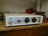
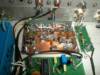
(click to enlarge)
Ergonomics
To make the operating very simple, it is used two 6-position rotary switches on front panel :
- the first one switches the audio signals, with the following positions : subcarrier off, subcarrier on, each of the three audio inputs, and, in the last position the 1000 Hz tone generator.
- the second switches the video signals : video off, each of the four video inputs, and in the last position the local pattern generator.
A 12 V DC, 400 mA was added on front panel because that proves very practical to power small CCD cameras, without using their separate wall transformer.
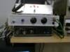
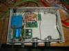
(The control box in the station. The box at the top, with its three red leds, is the 28 V AC
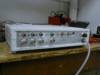
remote power supply of the 2.3 GHz transmitter which is in the immediate vicinity of the antenna)Switchings
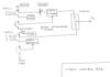
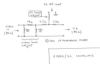
They are carried out in the simplest way, thanks to two 2-pole, 6-position rotary switches. The first circuit switches the video or audio inputs. The second circuit switches the power supplies : audio subcarrier on/off, pattern generator on/off, as one can see it hereafter in the synoptic.
Synoptic
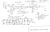
The 6.5 MHz subcarrier generator
The oscillator is of Colpitts type. To modulate the oscillator in frequency, it is used a 1N4007 rectifier diode because the varicap diodes type BA102 become unavailable. With the proposed schematic diagram one obtains a very linear variation curve, with a 165 kHz/V slope @ 6500 kHz. The optimum operating point is for U = 4,5 V. A second transistor is used as buffer. It feeds a band pass filter, composed of two LC circuits to the critical coupling, which ensures us a suitable spectral purity of the signal and the absence of intermodulation on the video signal which would be created by the modulator.
On the audio signal side, a first operational amplifier is employed as a matching transformer. It is followed by the traditional 50 µs preemphasis cell. After a new impedances adaptation, one finds a 3rd order low pass filter, whose cut-off frequency is 6000 Hz with a 18 dB/octave slope. The Vcc/2 half-power supply necessary to the operation of the unit is provided by an operational amplifier as a follower. The choice was made to cut the audio frequencies higher than 6 kHz at the transmitting end, because their presence was not considered to be really necessary for a use in traditional amateur television.
the schematic diagram
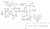
The 1000 Hz tone generator
The 1000 Hz tone generator is built with a very widespread CMOS circuit, the CD4060 which is a oscillator-divider. The frequency of a 4096 kHz crystal is divided by 2^12. With only 7 components, we obtain a square signal whose stabilities in frequency and amplitude are exemplary. A second-order low-pass active filter, using a simple transistor, transforms this square signal into sinusoidal signal.
NB: the sinusoidal signal has a little bit "sharp" shape because the third harmonic of the 1 kHz is only -30 dB below the fundamental. A 4th order filter, i.e. with two cells (but not completely identical to this one), would make it possible to obtain a quasi-perfect shape. But for the considered use, the shape obtained with a simple second-order filter is completely satisfactory.
To avoid any pollution of the video signal, the 1000 Hz oscillator and especially its 4096 kHz crystal were distant in the box of the wires carrying video signals. Decouplings were neat. No trace of 4096 kHz is detected with a spectrum analyzer on the video output of the control box.
Multiplex assembling and levels set-up
The assembly of the multiplex video + audio is very simply carried out by means of a resistive coupler, by taking care to respect the impedances on the accesses.
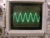
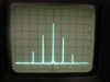
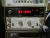
In the South of France, FM ATV transmitting and receiving follow the Astra/Eutelsat satellite television standard. The modulation index of the RF carrier by the audio subcarrier must thus be equal to 0.26. A rapid consultation of the values of the Bessel functions (the simplest way is to use the Excel function BESSELJ() ) indicates that the amplitude of the central line is J0 (0.26) = 0.9832 and that the amplitude of the two lines which frame this central line is J1 (0.26) = 0.1289. The relationship between these two values is equal to17.6 dB. We will thus adjust the injection resistance of the signal, on the assembling section, in order to observe this ratio of 17.6 dB approximately between the lines. Control is done by means of a spectrum analyzer. Below, the RF spectrum at 2320 MHz, obtained on my old HP141T.
When one does not have a spectrum analyzer, one can carry out an approximate adjustment by seeking the subcarrier level which causes the beginning of audio clics to the reception and by set up the level with a value 1,5 times higher.
Conclusion
This small video control box is easy to build and daily gives great services at the station. Next step: addition of the pattern generator.
Let's switch on our soldering irons!
B5+ et 73 de Jean-François Fourcadier, F4DAY
As you can guess, english is not my mother-tongue. If you are living in UK or in the USA or in another english language country, you can help me to improve the quality of my website. Just send me an emailwith the mistakes you have detected (the biggest first ! ). Even one or two corrected sentences will be greatly appreciated. Thank you for your help !
© 2000-2004 J.F. Fourcadier F4DAY