|
Jean-François
FOURCADIER |
|
|---|
|
Jean-François
FOURCADIER |
|
|---|
| write
to me ! |
© 2000-2004-
J.F. Fourcadier
|
welcome page |
| high speed data | television | antennas | microwaves | repeaters | miscellaneous |
(description published in the french journal "Mégahertz", January 2001)
The project started from a simple idea: taking into account the performances of the modern components, it sould be possible to produce in little time a small 2.3 GHz oscillator on a double face epoxy circuit ..... Then, after I succeeded, to try to modulate it in frequency, then to produce a genuine modulator, then to stabilize the frequency of the oscillator by means of a phase locked loop, and finally to make a small TV DX with such a device!
As often, one will not then fail to rewrite the story by ordering the ideas, conceptualizing them, in short while trying to make believe that all was clear and obvious upon the departure......
The technology :The Surface Mounted Components (SMC) are very widespread today in the retail trade and the mail order business. One can even salvage them on electronic discarded printed circuits. This last possibility is interesting for the more " expensive " components like capacitors of middle or high values. A computer mother board conceals several tens of them. To salvage them properly, one needs two soldering irons and the help of an assistant equipped with a pair of little pliers.
(click to enlarge)
SMC components appear to have completely honourable characteristics until frequencies of several GHz. To be convinced is easy : a small piece of printed circuit, a piece of UT-141 semi-rigid coax and two 100 ohms SMC resistances make it possible to build a small 50 ohms load with acceptable performances until in the microwave region for an unbeatable price:
One can be more ambitious and realize, by simple soldering of SMC components, more complex assemblies. The components are soldred in the air, directly between them, without connection wires. The copper face of an epoxy plate is used as ground plane. All SMC components having to be grounded are directly soldered onto the plan which ensures at the same time mechanical rigidity. To avoid mechanical constraints on the components, the connections with the external world (power supplies, audio signals, ...) are carried out using thin copper enamel wire salvaged on an old diskette drive engine. A large lighting magnifying lens bought in a hypermarket avoids headaches and a small device quickly build with two springs allows to immobilize two SMC the time of their soldering.


The schematics diagram :The oscillator is a Pierce type and uses a SMC BFR93A transistor whose the transition frequency is 6 GHz. This transistor is very widespread and costs only one or two euros. The tank circuit consists of a simple twist, of which the length conditions the operation oscillator frequency. One can thus very simply adjusts the frequency between 1 and 3 GHz by means of cutting pliers. For an operation on 2.3 GHz, the length of the twist is approximately 18 mm. The BFR93A transistor is soldered tilted so that its emitter can be soldered directly on the copper plane. An Agilent MSA08-86 MMIC is used as buffer and furthermore increases the output level.
(click to enlarge)
The frequency modulation method is simple but effective : By simple action on the base current of the oscillator transistor, one obtains more than 100 MHz of control, with a variation curve of the following shape :
The variation is not perfectly linear, but with an FM deviation limited to + / - 8 MHz the result is completely acceptable for current ATV applications. It will be observed that the slope is negative, i.e. that to an increase in the input voltage corresponds a frequency reduction. It is not the convention generally adopted in television and it will thus be necessary to reverse the signal somewhere between the output of the video camera and the oscillator.
One will be able to test the operation of the oscillator with television signals by means of the simple following injection device. The frequency variation slope at the operating point is 16 MHz/V, and this provide for a standard video signal (1 V pk to pk) a FM deviation similar to the Astra TV satellite standard (16 MHz pk to pk) :
Always for test purposes, the obstacle of the negative slope - which leads to an inverted video signal - can be circumvented by tuning the receiver on one of its spurious responses called "image frequencies". Explanation: The satellite demodulators operate usually with supradyne mixing and an intermediate frequency of 479.5 MHz. If we thus tune our receiver on a frequency of 1361 MHz, the local oscillator of the receiver will provide a signal of 1361 + 479.5 = 1840.5 MHz, and we will be able to observe an infradyne response on 1840.5 + 479.5 = 2320 MHz. In the operation, the received spectrum is reversed, and the video is thus also reversed. One can thus very easily observe the picture quality. A genuine inverter modulator is however preferable. The circuit presented below is an example. A CCIR 405-1 preemphasis cell is placed at the input. The circuit offers the ability to connect later a frequency stabilization circuit by means of a phase locked loop.
The oscillator operates very well without PLL, with a frequency which is maintained within + / - 1 MHz over short periods. This is sufficient for Wide FM television tests. A frequency stabilization is however highly wishable. The circuit shown below using a Motorola IC MC12179D is extremely simple. A small quarter wave line made out of semi-rigid coax plays the role of impedance transformer to avoid excessive loading of the output. The PLL is locked at a frequency equal to 256 times the crystal frequency. A 9 MHz crystal led to a locking frequency of 9 x 256 = 2304 MHz. We will use here a CB crystal of 27.185 MHz, overtone 3, which thus has a fundamental frequency close to 9062 kHz. One thus gets a locking on 2320 MHz.
NB: With the experience, the 9 MHz oscillator appears very slightly " a little high " (overtone effect !). For a precise operation on 2320.0 MHz, a 27.175 MHz crystal is preferable.
On pin 6 of the integrated circuit one gets the control signal of the VCO, which must be filtered through a phase compensation network (220 W, 820 W, 47 µF). This network ensures the stability of the loop.
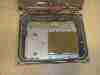
The achievement :
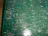
As mentionned above, all the ground points for the SMC components are soldered directly on the copper of an epoxy plate, which one will be carefully pickled. The realization of the twist, which is used as microwave resonant circuit is extremely simple :
The assembly will be imperatively placed in a metal case. Without PLL stabilization circuit, the stability obtained over short periods is about + / - 1 or 2 MHz and is thus sufficient to carry out amateur television tests.

In the above realization, the oscillator case is sheltered in an outdoor box to be able to resist the rain and to thus authorize an installation in the immediate vicinity of the antenna. A place is reserved in the box for the future addition of a 500 mW amplifier.
Adjustments :
The oscillator starts immediately after power on. If one builds the assembly including the frequency stabilization, one will first cut the AFC wire towards the transistor base to make this one inoperative. The fine tuning potentiometer is set up at half-course. One measures the oscillator output frequency with a frequency counter. Without a suitable counter, you can use a satellite receiver, by taking in account his spurious responses (cf supra).
One then adjusts the length of the twist by means of cutting pliers to obtain the correct frequency, within a 10 MHz margin.By closing again the AFC loop, the PLL locks immediately. The RF output power is about 20 mW. The deviation control potentiometer is simply set up for a satisfactory picture quality on a TV monitor.
Using the device :The local tests do not present any difficulty : a simple coffee can antenna (2.3 GHz version of the express-pizza antenna) and one gets easily more than a 100 meters range with an excellent picture quality.
Consequently, with these 20 mW, why not try a small DX ? I'm lucky to have not far from my home and in line of sight, an ATV repeater : the mount Aigoual repeater F5ZGN (F5AD website) is at a distance of a little more than 50 km, has an input on 2320 MHz and an output on 1255 MHz. It's a little far, so we need a medium gain antenna. A tea can is naively assembled, without special care at the focus of a standard 80 cm ( 30" ) satellite dish. The illumination of the paraboloid is probably not optimum and the theorical 23 dB gain not available.
The experimental unit is assembled on the balcony of the 2nd floor. The wood mast is a little short with for consequence that a roof makes a partial obstruction of the beam and the Fresnel zone clearance is not good ! One connects the video source, the power supply, one aims the antenna toward the repeater and miracle..... that works ! Of course the picture is very noisy, but colored and the people recognizable. Hopeful !
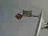
The next steps are now to increase the RF power from 20 mW to 600 mW by the mean of a power amplifier using an ITT 2303 IC and a better integration of the system (power supply, outdoor cabinet, connections, antenna, ...).The outdoor cabinet and details of the feeding:
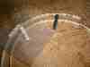
The antenna on my balcony :
(notice below the dish, the expres-pizza antenna for the1,2 GHz feed back of the remote repeater)

Conclusion :
This small transmitter for the 2.3 GHz band is only an example of what it is possible to realize in the field of the low microwave segment, at a very low cost. No expensive substrates, not of engraving, some common salvaged components and the results are often there, surprising!
Let's switch on our soldering irons !
B5+ et 73 de Jean-François Fourcadier, F4DAY
As you can guess, english is not my mother-tongue. If you are living in UK or in the USA or in another english language country, you can help me to improve the quality of my website. Just send me an emailwith the mistakes you have detected (the biggest first ! ). Even one or two corrected sentences will be greatly appreciated. Thank you for your help !
© 2000-2004 J.F. Fourcadier F4DAY