|
Jean-François
FOURCADIER |
|
|---|
|
Jean-François
FOURCADIER |
|
|---|
| write
to me ! |
© 2000-2004-
J.F. Fourcadier
|
welcome page |
| high speed data | television | antennas | microwaves | repeaters | miscellaneous |
A two tone generator to check the linearity
of the components of a video transmission chain
As the amplitude-frequency response and the group delay distortion, the linearity is an important characteristic of a video transmission chain. A bad amplifier linearity, or a lack of linearity in AM or FM modulators, discriminators,... is prejudicial to the quality of the pictures (unsaturated colors) and provoke bothersome shortcomings when one tries to transmit two audio sub-carriers. The method of assessment of the linearity that is proposed here requires the use of a small two tones tones generator easy to build and a spectrum analyzer or a low cost discarded selective voltmeter.
The proposed method
The method proposed here is known for a long time of the transmission specialists. It is used to qualify the SSB transmitters and was, no long ago, used to measure the performances of analog microwave links. It consists in injecting, in the chain or in the device to test, two sinusoidal signals with a relatively important level, and to observe the spectrum of the output signal. So, if all was OK, one would recover in the output the two original sinusoidal signals, and nothing else..... However such an input signal is especially aggressive and a bad linearity, even very low, will create detectable intermodulation products. Indeed, when a device is not perfectly linear, it also behaves as a mixer, and signals at different frequencies are created.Let's illustrate the subject by an example:
To test the linearity of a video amplifier, let's inject simultaneously on its input two sinusoidal signals at the following frequencies: F1 = 4000 kHz and F2 = 3686 kHz.
If the amplifier was perfect, we should recover on its output these two amplified signals and nothing else. The perfectly linear amplifiers do not exist, so we will recover on its output, in addition to the useful signals, intermodulation (or mixer) products. One usually distinguishes:
- second order intermodulation products, at the frequencies:F1 - F2, either 4000 - 3686 = 314 kHz, in this example,
F1 + F2, either 4000 + 3686 = 7686 kHz- third order intermodulation products, at the frequencies:
2*F1 - F2, either 4314 kHz
2*F1 + F2, either 11686 kHz
2*F2 - F1, either 3372 kHz
2*F2 + F1, either: 11372 kHzThe most bothersome products will be those that fall in the video band, at the frequencies:
F1 - F2, 2*F1 - F2 and 2*F2 - F1.
The linearity of the amplifier will be simply evaluated by measuring the relative levels of the 2nd and 3rd order intermodulation products, respectively to the useful signals, for a given ouput level.
Realization of the two tone generator
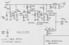
Schematic diagram:
(click to enlarge)
The proposed two tones generator is constituted of two channels: a channel at 4000 kHz and an other channel at 3686 kHz.
A cheap 4000 kHz computer crystal is inserted in an oscillator made with a BC546B transistor. The produced signal is amplified with a second BC546B transistor. A band filter, composed of two coupled circuits with a slight under-critical coupling, improves the spectral purity of the signal. Finally a 2N2219A transistor in common collector scheme insures a very low output impedance that guaranties a good isolation between the two channels. The second channel is identical, but with a 3686 kHz crystal.
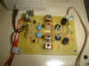
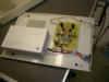
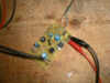
The two channels are coupled by two 150 ohms resistances that are seen in parallel by the output. The output impedance of the installation is thus 75 ohms, purely resistive. Two 4.7 kohms adjustable resistances permit an adjustment and a balance of the levels for the two channels.Realization:
Download the printed circuit in the Ares format (zipped)
The coils are all identical. They present an inductance of 7.8 µH +/- 30% adjustable thanks to an adjustable slug. They are achieved on discarded slug tuned forms (Coilcraft).
NB: IF transformers from 10.7 MHz IF should be suitable.
The form includes 4 small pulleys. A total of 4 x 8 = 32 turns of enameled wires are wounded to get a resonance frequency of 3.8 MHz with a 220 pF capacitor.
Set up:
The operating is immediate. One observes the output signal on the the spectrum analyzer or on the selective voltmeter, one adjusts the slugs to the maximum of signal on the two frequencies 4000 kHz and 3686 kHz.
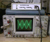
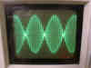
One then adjusts the adjustable resistances to get on the oscilloscope a 1200 mV pp signal, and one check again that the levels on the two channels are identical.the output signal on an oscilloscope:
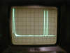
and on a spectrum analyzer:
vertical set up: 10 dB / division, horizontal: 500 kHz / division
the peak on the extreme left marks the zero frequency
On the right, one can perfectly distinguish the two peaks at 3686 kHz and 4000 kHz
When we adjust the output level to 1200 mV pp, we get:IM2 <- 60 dBc
IM3 <- 60 dBc
harmonic <- 30 dBcWe will see that this performance level is more than sufficient to qualify our small amateur equipments.
Use
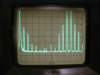
- test of a video amplifier (badly designed !)
While adjusting its gain to the minimum, we get in output a more or less acceptable signal:
One get a 2nd order intermodulation level at 314 kHz, - 45 dB under the carriers and 3rd order intermodulation level at 3372 kHz and 4314 kHz, - 47 dB under the carriers.
But when one set up its gain to the maximum, to get 1,7 V pp on a 75 ohms load, the result becomes fairly unacceptable:
The acceptables thresholds in amateur television
The topic is difficult and controversal !
At the amateur level, the research of a good linearity must be probably seen more like an axis of improvement of the equipments that as an end in itself.
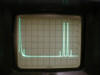
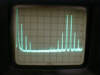
To give an order of size, the twist oscillator used daily at the station and that transmits pictures of rather fair quality, produces in local the following spectrum when it is feeded by the two tone generator:
The 2nd order intermodulation level is at - 15 dBc and the 3rd order at - 25 dBc. The predominance of the 2nd order is presumably due to the parabolic shape of the voltage-frequency characteristic of this very simple VCO.
When one wishes to transmit two audio sub-carriers, the level of requirement increases. Some tests should be done to determine the acceptable threshholds.
Conclusion
With this little, easy to build, two tone generator, we have a tool able to better know the linearity of our video homebrewed equipments. It will permit to improve the quality of the amplifiers, but particularly of the modulators-VCO whose characteristic is often far from being satisfactory.
For the study of the linearity, the proposed method is more general than the one that consists in using a Vertical Insertion Test Signal (VITS) generator and analyzer (very rare equipment in the amateurs shacks). The method is simple and efficient. It will agree merely to be prudent in the analysis when the signals cross clamp devices.
Finally, the method opens the way to the design of matched correction devices (predistorsion networks). But there it is another business!
To follow.....
B5+ et 73 de Jean-François Fourcadier, F4DAY
As you can guess, english is not my mother-tongue. If you are living in UK or in the USA or in another english language country, you can help me to improve the quality of my website. Just send me an emailwith the mistakes you have detected (the biggest first ! ). Even one or two corrected sentences will be greatly appreciated. Thank you for your help !
© 2000-2004 J.F. Fourcadier F4DAY