|
Jean-François
FOURCADIER |
|
|---|
|
Jean-François
FOURCADIER |
|
|---|
| write
to me ! |
© 2000-2004-
J.F. Fourcadier
|
welcome page |
| high speed data | television | antennas | microwaves | repeaters | miscellaneous |
experimental 2 Mbit/s modem (receiving part)
The present article follows the set of articles "High speed data signaling project (2 Mbit/s)", on this website. We describe here the receiving section of the modem.
The modem is a device that one plugs on the rear connector of any simple and inexpensive satellite receiver used as a 23 cm receiver, and that provides a NRZ signal at a 2 Mbit/s rate, with its clock. Besides this modem provides a signal representing the bit error rate.
An interface with the outside world (USB port?) will be implemented subsequently.
Modem structure
After the Nyquist filter and a video amplification, a fast comparator distinguishes the "0" and the "1" of the biphase (Manchester) signal received.
The recovery of the rhythm is made by a full wave rectification of the received signal - what makes appear a stripe at twice the clock frequency-, while amplifying the signal in a selective amplifier set up on 4096 kHz, then injecting this signal in a phase locked loop to get the recovered clock.
Finally a logical processing of the biphase signal converts it in a NRZ signal, and detects the biphase violations to detect possible transmission errors.Schematic diagrams
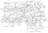
Analogue section:
(click to enlarge)
The first BC546B transistor operates in a common collector scheme. It isolates the Nyquist filter and guarantees the impedance on the access. The role and the behavior of the Nyquist filter have already been described. The three following transistors constitute a video amplifier assigned to rise the signal to the appropriate level for the LM360 fast comparator and the full wave rectifier. This last is composed of a transistor in a common emitter scheme, with a gain of 2. It is polarized in order to amplify and to invert only the positive half wave. A summing with the incidental signal is achieved in a potentiometer that permits to adjust the symmetry of the signal. The rectified signal, that includes a strong component of 4096 kHz, is amplified in a selective amplifier builded around a BF240 transistor and a LC circuit. A capacitive tap gives the right level for the PLL circuit 74HC4046. Notice the C-R cell constituted with a 15 pF capacitor and a 2.7 kohms resistance to get a phase advance of 45 degrees of the 4096 kHz signal before feeding the PLL circuit. This cell is necessary to get a correct sampling, at the precise instant of the maximum of opening of the eye. With the given values, the measured capture range is plus and minus 100 kHz around the central frequency, what is sufficient to assure an efficient locking in any case, and this in spite of the possible instabilities of the RC drived VCO frequency.
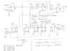
Logical section:
This section achieves the biphase to NRZ conversion and return a signal representing the bit error rate of the transmission.
The D flip-flop U3A controled by the 4096 kHz clock from the analogue section regenerates the biphase signal. A division by two of this 4096 kHz clock frequency by the U4A flip-flop recovers the original 2048 kHz clock. Finally, the U4B circuits, U9A, U7D,U6A, U9B and U3B transform the biphase signal in NRZ signal: Thanks to the U4B shift register, the exclusive OR U9A provides a logical one for every transition of the biphase signal, which occurs inevitably in the middle of the transmitted bit. The periodic apparition of this logical level assures the suitable phase of the frequency divider by two, U6A. It is then sufficient to multiply this clock signal with the incidental signal, with the help of the exclusive OR U9B, to get the original NRZ binary signal transmitted. U3B regenerates then the result for a perfect shape.
The transmission errors detection lays on a scheme, very known of the specialists and very simple of implementation. The biphase (Manchester) signals have the property to have always a transition in the middle of the transmitted binary symbol. All deviation to this absolute rule of construction is called a "biphase code violation". Of course, there is no biphase code violation on the transmitting side. All biphase code violation on the receiving side is therefore the evidence of a transmission error. The processing is simple. The received biphase signal passes through a 3 cells shift register, constituted with the three D flip-flop U4B, U5A and U5B. Every succession of three zeros or three ones reveals an absence of transition and therefore a biphase code violation. It's the role of the three inputs NAND gates U8A and U8B to detect them. One can get thus an appreciation of the quality of the transmitted signal quality with a simple counter connected at the output of U7B.NB: It would be subsequently interesting to give a logarithmic shape to the error rate and to arrange on the modem a bargraph, monitoring the transmission quality......
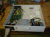
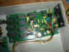
Achievement
The used components are quite banal and extensively available in detail shops. Being about a prototype, no printed circuit has been achieved for the time. A Veroboard acts as support. The circuit is compact, some place remains in the box to add subsequently the interface with the outside world. A particular attention will be brought to the decouplings and the power supplies. The circuit uses "nervous" components and the usual rules for RF circuits must be observed (many ceramic and multilayer capacitors are not visible on the photos because they are soldered directly on the components pins, on the back side of the card!).
(click to enlarge)
Set up
One set up first the 2.2 kohms potentiometer to get a signal which the frequency is precisely 4096 kHz on the pin 4 of the PLL circuit 74HC4046.
A "video" signal, in fact a 2,048 Mbit/s binary signal, biphase coded, with an amplitude of 1 V peak to peak, is then injected to the input of the modem. It is generated by our previously described pseudo-random generator.
The 1 kohms level potentiometer is adjusted to get 1.5 V peak to peak at point A. The symmetry and equalization are adjusted to get a symmetrical signal on the base of the BF240 transistor. The 18 µH inductance is adjusted for a maximum of sinusoïdal signal @ 4096 kHz on the pin 14 of the PLL circuit 74HC4046. The phase locked loop locks itself without problem and assure a very low phase jitter of the recovered clock.
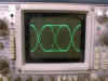
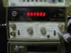
One should verify that the sampling is done for the maximum of the eye opening. It corresponds to a positive going transition of the clock signal situated precisely in the middle of the available symbol on the output of the LM360 comparator. If needed one may modify VERY slightly the set up of the symmetry and/or the core of the tuning circuit to get this result. Attention, for the measurement, the two oscilloscope probes should be identical and should have the same cable length !
(on top the 4096 kHz clock signal, below the signal provided by the comparator,
for a correct set-up)
Tests on the air
After the set up described higher, the scheme is perfect for local tests. The ATV repeater F5ZGN of the mount Aigoual (Gard-France) that is situated 50 km away from my station is used. My previously described "twist" ATV transmitter - frequency 2320 MHz, output power 600 mW, 80 cm dish - is FM modulated by the biphase signal provided by the pseudo-random generator. This signal is received by the repeater, and then broadcasted on 1255 MHz FM in the whole region, as if it was amateur television.
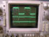
After two path of more than 50 km, two transmitters and two receivers crossed, the signal comes back to its starting point, with some impairements, mainly linearity and amplitude-frequency response problems. The available signal on the rear connector of the satellite receiver has the following shape:
This type of behavior of our equipments is not very good either for amateur television and is relatively easy to solve. It will be necessary that we worked on. But there is not an emergency, in the case of our digital transmission the eye remained very well open, the modulation is robust, the fast comparator sorts out the zeros and the ones, and the modem PLL follows vigorously the received signal!
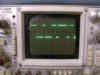
On the left the NRZ code received, on the right the counter connected on the error detection output stays on zero:
And on a traditional ATV receiver, wthat can we see during this digital transmission at a 2 Mbit/s rate ? A kind of granular noise, unable to synchronize the television set. But it is not because one doesn't see a picture, that there is not an big quantity of information that is broadcasted!
What next ?
One can say today that the concept is validated. It is characterized by its simple implementation, its efficiency on the air, and by the use of reliable and well known equipments of amateur television.
The tasks that are to achieve are the following:
- to improve the modem, for example by using differential biphase code to avoid to have to specify the direction of the modulation,
- to achieve printed circuits,
- to construct a true hardware and software interface for PC, the ideal being to be able to introduce and to extract the data by an USB port,
- finally, to work on the regeneration of the digital signals in the repeaters, in order to avoid the cumulative effects of the noise. It is one of the big advantages of the digital transmission that to be able to recreate in every repeater quasi-perfect signals from noisy or impaired signals.
It could be funny to experiment the whole scheme on more of two ATV path, while transiting for example by other ATV repeaters of the neighbourhood, and using 10 GHz ATV links of the region. Ranges of more than 200 km is certainly possible, and it is quickly controllable. Could one then imagine transmission tests at a 2 Mbit/s rate between Montpellier, Nîmes and Marseille (french cities in the South of France), for simple technical tests in a first time, then more seriously to exchange voice, pictures, files or MPEG video?to be continued, stay tuned......
B5+ et 73 de Jean-François Fourcadier, F4DAY
As you can guess, english is not my mother-tongue. If you are living in UK or in the USA or in another english language country, you can help me to improve the quality of my website. Just send me an emailwith the mistakes you have detected (the biggest first ! ). Even one or two corrected sentences will be greatly appreciated. Thank you for your help !
© 2000-2004 J.F. Fourcadier F4DAY