|
Jean-François
FOURCADIER |
|
|---|
|
Jean-François
FOURCADIER |
|
|---|
| write
to me ! |
© 2000-2004-
J.F. Fourcadier
|
welcome page |
| high speed data | television | antennas | microwaves | repeaters | miscellaneous |
A Smeter for your satellite receiver :
to evaluate the relative received levels
Introduction
To be able to evaluate the relative level of a received signal is always very useful : to aim an antenna, to optimize its polarization or to compare the received signal strength from various correspondents, the small modification described below will be very useful. It is not a true l S-Meter, because for reasons of simplicity, one will limit itself to measure the AGC voltage of the satellite receiver tuner by means of a traditional digital voltmeter.
In this point, we are (almost) sure of only one thing: the measured voltage and the signal strength vary in the same direction !
ModificationCaution: inside the receiver cabinet some accessible parts are to the main voltage. To achieve the described hereunder modification, you must take the suitable precautions.
- after having unpluged the main, open the receiver cabinet,
- identify the receiver tuner: it's very simple, it is usually bound of the F socket on which is connected the coaxial cable to the satellite LNB,
- unscrew the screws that fix the printed circuit of the receiver on its metallic frame,
- turn the printed circuit and localize the connections points of the tuner on the printed circuit,
- isolate the printed circuit and the different active parts from accidental contacts, by means of pieces of wood or cardboard,
- connect the common wire of a digital voltmeter to the metallic frame by means of an alligator clip,
- switch the voltmeter on the 20 V or 30 V DC range,
- reconnect the receiver to the main, very carefully,
- test the different connection points of the tuner on the printed circuit until you localize a point where the voltage varies according to whether the satellite LNB is plugged or no. Typically, the voltage varies from a fraction of volt to two volts,
- unplug the main again,
- bore two 8 mm holes on the rear panel of the cabinet to fix two 4 mm banana sockets,
- connect by means of wires the banana sockets : a wire to the ground, a wire for the AGC voltage,
- to avoid to introduce some troubles in the receiver, it's prudent to put in series with the AGC wire a 10 kohms resistance.
-.... and of course don't forget to close again the cabinet, with the screws you won't have lost during the time (! )
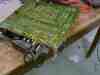
PhotographsThe connections to the receiver :
(click to enlarge)
The connections to the banana sockets and the 10 kohms resistor :
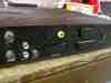
The rear panel of the receiver :
B5+ et 73 de Jean-François Fourcadier, F4DAY
As you can guess, english is not my mother-tongue. If you are living in UK or in the USA or in another english language country, you can help me to improve the quality of my website. Just send me an emailwith the mistakes you have detected (the biggest first ! ). Even one or two corrected sentences will be greatly appreciated. Thank you for your help !
© 2000-2004 J.F. Fourcadier F4DAY