|
Jean-François
FOURCADIER |
|
|---|
|
Jean-François
FOURCADIER |
|
|---|
| write
to me ! |
© 2000-2004-
J.F. Fourcadier
|
welcome page |
| high speed data | television | antennas | microwaves | repeaters | miscellaneous |
A good pre-emphasis for the Comtech TV module !
One can find easily on the market these small attractive Comtech TV modules: video input, output on 2,3 GHz, small size, low cost, etc... However these modules have a problem when one tries to use them for ham radio applications, because most of our receivers are complies with the ITU 405-1 de-emphasis standard . If one feeds the module with an external pre-emphasised signal, the colors are torn, if one modifies the level to avoid these phenomena, the picture becomes excessively dark. If one feeds the module directly with a non pre-emphasised video signal, the colors are noisy. Worse, after crossing through an ATV repeater, the signal is often seen in black and white. In short, something is wrong.
To cure the problem, one can try to modify some parameters or some components empirically outside or inside the module. The solution that is proposed here results from a methodical approach based on measurement and on the synthesis of a equalisation network. The Comtech module used for the survey bears the FM2400TSIC reference, but the results are probably transposable to the other produced of the brand.
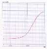
The amplitude-frequency response
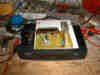
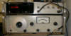
We'll go to measure the amplitude-frequency response of an unmodified Comtech module. One will connect the video input of the module on a low-frequency generator, and one will observe the received signal, for lack of a measurement receiver, on the video output rear connector of a home satellite receiver, which is equipped with a ITU 405-1 de-emphasis. A 75 ohms load and an oscilloscope destined to observe the quality of the signal come to complete the device. The differences of video levels are read on a video "gain-phase meter", model HP3575A.
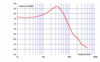
The level remains practically steady between 10 kHz and 100 kHz. After a bump culminating to + 2,7 relative dB at a frequency of 300 kHz, one observes a regular fall until - 1,3 dB at 5 MHz.
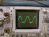
One will observe on the way on the scope that the Comtech module has a very bad behavior below 1 kHz, with a strong non linearity at the low frequencies and a bad amplitude-frequency response. But we don't lose the synchronization of the frames.....! We'll have to work later also on that side!
the signal at 500 Hz !
On the other hand, positive point, one doesn't meet any difficulty to achieve a broad FM satellite modulation, Eutelsat/Astra type, with a +/- 8 MHz swing.
The equalisation network
The ideal response of the transmission chain is of course a perfectly flat curve at 0dB in the whole video band. The absolute level can be adjusted by the main gain potentiometer. To correct the bad amplitude-frequency response, we'll insert a small equalisation network outside of the module, on the path of the video. The response curve of this network should be precisely opposite of the one of the Comtech module. The network should present an impedance of 75 ohms when it will see itself 75 ohms. Considering the input impedance of the Comtech modules that is badly definite, a resistance of 82 ohms will be added to the input of this one.
At the cost of long calculations and long tests, it is certainly possible to approach very close the perfectly matched quadripole for the equalisation. To simplify the synthesis, we will here limit ourselves to the equalisation of the 4 dB of fall observed between 300 kHz and 5 MHz. We will use a minimal phase structure analogous to the one of the ITU networks. The calculation is done by simulation with the free Spice software called Spice Opus described in particular in a previous article on the pre-emphasis. After ten minutes of gropings one gets a very appropriate result (response curve, impedances on the access,...) with the following network :
NB: These values are suitable for 625 lines TV systems.
The response curve of this network is as following:
When one places such a equalisation network in the path of the signal video feeding a Comtech module, the 4 dB of fall in high frequency is compensated, and the amplitude-frequency response becomes flat to + / - 0,6 dB in the whole band until 5 MHz.
For the readers interested by the complete features of this network, the Spice "netlist" is:
Comtech 405-1 equalisation
* comtech.cir file
* author: J.F. Fourcadier, F4DAY
.control
ac lin 201 45KHz 9MegHz
let phase = vp(4) + 2*pi*(vp(4) lt 0) - 2*pi
plot phase/1.57 xlog xlabel f_[Hz] ylabel phase_[plat]
GD = -1e9*2*(phase[1,200] - phase[0,199])/(45000*2*pi)
plot GD xlog xlabel f[Hz] ylabel group_delay[ns]
unlet phase
plot 10*log(4*(vm(4)^2)) xlog xlabel f[Hz] ylabel response[dB] ylimit -6 1
plot -real(vm(2)/i(v1)) -imag(vm(2)/i(v1)) xlog xlabel f[Hz] ylabel impedance ylimit 0 100
.endc
* voltage resources
v1 1 0 dc 0V ac 1 sin 0 1V 20megHz
* resistors
ri 1 2 75
r1 2 3 75
r2 3 4 75
r3 3 5 100
r4 2 4 56
ro 4 0 75
* capacitor
c1 2 4 1800pF
* inductance
l1 5 0 10uH
.endOne will note on the way that such a network, possibly modified by means of the tool described above, can be used to correct ATV repeaters or various equipments whose amplitude-frequency response is not satisfactory.
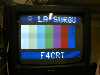
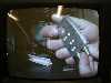
The results on the air
(click to enlarge)
NB: The pictures shown above are received after two jumps:
Transmission on 2.3 GHz from the F4CRT station, Isle-sur-Sorgue (Vaucluse, south of France), received by the ATV repeater F5ZGN of the Mount Aigoual (Gard, south of France), distance 120 km. F4CRT: ATV Comtech module corrected as mentionned, , 4.5 W RF amplifier, antenna : 90 cm dish.
Retransmission by F5ZGN on 1.2 GHz and receiving by F4DAY in Montpellier (Hérault, south of France), distance 50 km
Sorry for the bad quality of the pictures (reflections of the room lamp,...)!
In summary
The TV Comtech modules preemphasise the signal, but according to a different law of the one definite by the ITU 405-1 recommendation. When one wishes to operate these modules in link with receivers deemphasising the signal in accordance with the recommendation, one can correct the signal of the following manner:
- don't open the module, do not to remove nor short-circuit components inside the module,
- soder a 82 ohms resistance on the video input of the Comtech module to fix its input impedance,
- remove the possible external pre-emphasis network situated elsewhere in the video path (amplifier,...),
- insert the pre-emphasis network described above in the video path toward the Comtech module. One will notice that by its structure, the pre-emphasis network could take the place of an eventual external pre-emphasis network (2 resistances to replace). Easy....
- And of course adjust the video main level
Let's switch on our soldering iron !
and thank you to Michel, F4CRT, for his help and his numerous tests,and also to Dave Lauder G0SNO for his friendly help
B5+ et 73 de Jean-François Fourcadier, F4DAY
As you can guess, english is not my mother-tongue. If you are living in UK or in the USA or in another english language country, you can help me to improve the quality of my website. Just send me an emailwith the mistakes you have detected (the biggest first ! ). Even one or two corrected sentences will be greatly appreciated. Thank you for your help !
© 2000-2004 J.F. Fourcadier F4DAY