|
Jean-François
FOURCADIER |
|
|---|
|
Jean-François
FOURCADIER |
|
|---|
| write
to me ! |
© 2000-2004-
J.F. Fourcadier
|
welcome page |
| high speed data | television | antennas | microwaves | repeaters | miscellaneous |
Building an omnidirectionnal antenna for the 23 cm band
Introduction
To complete our amateur television repeater in construction, we need, considering the localization of the possible transmitting site and the zone to cover, of an antenna with the following features:
- working band 1240 - 1270 MHz
- horizontal polarization
- omnidirectionnal radiation pattern
- the higher possible gain.....
- realization with amateur meansOur first task was to examine what are the habits in the professional domain of TV broadcasting where the problems to solve are similar (although the easiness of construction is layed in different terms). In TV broadcasting, one often uses four coupled panels antenna and, in the biggest stations, a particular slot antenna called "superturnstile" or "batwing." A visit on the website of Kathrein teaches us that these exist for the 470-862 MHz band, can give up to16 dBi of gain - very interesting - but the height for these assemblies of 16 "bays" is 18 m with a weight of 3600 kg!
The Kathrein's UHF catalog page:
www.kathrein.de/de/bca/produkte/download/as_band45.pdf (88 ko).
Their conception, where all the parts are grounded, confers them an exceptional resistance to the atmospheric discharges; resistance to wind is also excellent. Unfortunately their feed systems, so much for the coupled panels that for the "superturnstile", lay on numerous accurate lines to define precise phase delays. The setup work is not negligible and the construction rather complex with amateur means.
Our choice :A research on the Internet (thank you to Alain, F1JFP for his documentary research) teaches us that two German hams DK 3 BA and DG 8 SG constructed in 1991 an antenna to the wished features and that a description has been given that year in UKW Berichte / VHF Communications magazine. By luck, the text of the article is downloadable and a small software is even provided to adapt the measurements of the antenna according to the precise needs of the reader. The german website German where one can download the original description and the software is : http://www.uni-duisburg.de/FB9/HFT/homepage-eng/afustationen-eng.html
We will opt for an 8 pairs of slot antenna, with in our precise case a central operating frequency of 1255 MHz. The waveguide's bottom part, close to the feed connector, is reduced in relation to the original model to limit the overall height of the antenna. One will find a schematic of the realization below:
The fact to increase the number of slot pairs increases the gain, but decreases the bandwidth. The assembly constitutes in fact an interferometer with a scattering behavior: a frequency change, for example by a wideband modulation, produces a deaiming of the antenna to the rhythm of the modulation and therefore a parasitic amplitude modulation on the receiver side. This phenomenon is well described in the easy reading paper presented to one symposium of the IEEE in 1998 by Shively Labs: http://www.shively.com/tb-uhf_antenna_choices.pdf
Eight slot pairs appear to achieve an appropriate tradeoff between the expected gain of 8,4 dBd, the bandwidth of 78 MHz for a SWR < 2 and the antenna height of 1.82 m. With 8 slot pairs, the deaiming parasitic phenomenon we describe higher is negligible.A construction trick
The RF energy is in fact transmitted in an rectangular section waveguide having radiating slots. The mechanical problem to solve is therefore to construct such a waveguide. The solution used by DK 3 BA and DG 8 SG consists in using a section of the nearest standardized shape available in the industry. Apart from it is only about an approximation capable to weaken the omnidirectionnal pattern, some attempts showed quickly that the purchase of such a section was not simple thing.
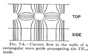
The book "Microwave Transmission Design Data" from Theodore Moreno (Dover Publication Inc, NY, 1948) provides us an interesting track while presenting us a cartography of the current lines in (on) the walls of a guide operated in the TE10 mode (it is our case):
The upper part of the diagram represents the waveguide large side, the bottom part, its height. For a good propagation of the wave in the waveguide, it is essential not to cut current flows. One deducts that a cut practiced on the entire length, in the exact middle of the large face, doesn't disturb the current flows. The things probably sounds more badly if one practices longitudinal cuts in the height or in the angles..... The slot openings come to disturb certainly a little the current distribution, but the experience shows that the effect is negligible.
From then on, the problems of construction are considerably simplified. It is sufficient to U bend two metal sheets and, after realization of the slots, to join them to build the waveguide, without big cares because the current is near zero through the junction between the two U.
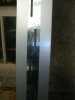
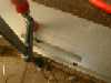
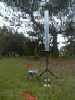
Some photographs are better than a long speech:The achievement:
realization Gérard F9YA, with the help of Christian F4CJM for the foldings,:

(click to enlarge)
The adhesive aluminum tape, of the type of the one used by the in air-conditioning specialists, assures the assembly of the two U. The tapes are available in rollers in many hobby and plumbing stores and have an excellent time behavior.
The feed device of the waveguide is achieved in brass, then silvered:
The final weather protection can be assured of various manners:
- introduction of the waveguide in a PVC tube, diameter 200 mm, but it is necessary to check the transparency of the PVC with a test in a microwave oven
- stopping of the slots by a thin material, RF transparent and non water absorbent
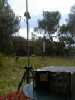
- introduction of the antenna in a polyethylene bag, Ultra Violet resistant (heavy duty trash bag)Characterization:For the SWR measurement, a directionnal coupler is arranged in the cable between a HP 8620A sweeper and the antenna. The measurements are made on a HP 8755C swept analyzer. The device is sweeped with a central frequency of 1260 MHz. The measured SWR is <1.2 between 1230 MHz and 1278 MHz (return losses> 20dB):
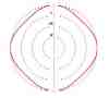
For the measurement of the pattern diagram in the horizontal plane one will arrange the antenna far from any obstacle. One will connect to a RF generator setup on 1255 MHz with a power of about 1 mW in the N connector of the antenna. The receiving is made about twenty meters away by means of a small "express-pizza" antenna and my old HP141T spectrum analyzer set up for a 2dB/division sensitivity.

One will then turn the antenna while noting the level variations according to the angles of rotation. The result is excellent: the received level doesn't vary more than + / - 1 dB in respect to the mean level and is therefore in all points in conformity with the expectations.
Attention: For the measurements, and later for the operation, it is mandatory to arrange the antenna perfectly vertical and to check its verticality by means of a plumbline. Indeed, the antenna produces a sharp beam aiming the horizon. If the antenna is not perfectly vertical the pattern diagram measurement will be wrong and one take the risk not to be received later by his correspondents.
The measurement of the relative gain in relation to the dipole has cannot be achieved with the same rigor, for lack of quality of the reference dipole we used. Nevertheless the relative gain has can be valued between 7 and 9 dBd, that is to say in conformity with the expectations. The measure of pattern diagram in the vertical plane is more complex and has not been achieved.Conclusion:
B5+ et 73 de Jean-François Fourcadier, F4DAY
As you can guess, english is not my mother-tongue. If you are living in UK or in the USA or in another english language country, you can help me to improve the quality of my website. Just send me an emailwith the mistakes you have detected (the biggest first ! ). Even one or two corrected sentences will be greatly appreciated. Thank you for your help !
© 2000-2004 J.F. Fourcadier F4DAY